Plastic Part Design
This page summarizes my learnings from my Udemy Course: Basics of Plastic Part Design for Design Engineers. Here, I demonstrate my knowledge with an example of a plastic part.
We will convert this CAD geometry into one that can be injection molded
Draft
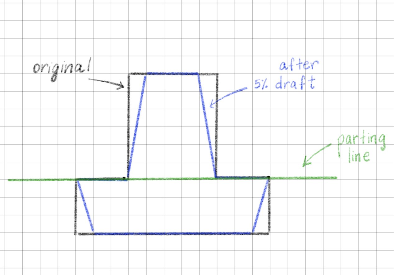
First, we figure out the parting line to create a draft.
The sketch shows the parting line and an exaggerated view of the draft angle.
We add a 5% draft on the cylindrical and side surfaces.
Fillet
Next, we add fillets and round the corners. The external fillet radius is at least 150% of the wall thickness.
Shell
We then shell the part to a wall thickness of 1.5mm.
Ribs
Last, we create internal ribs for support. The thickness of ribs is 40-60% of the wall thickness. Internal rib are also filleted to 0.5mm.
After this, our part has been designed for injection molding. Some parts may also require bosses for screws or locators in assemblies. Another thing to consider is the location of the ejector pins to avoid surface defects on visible or functional surfaces.


